
What Is a Wiring Diagram?
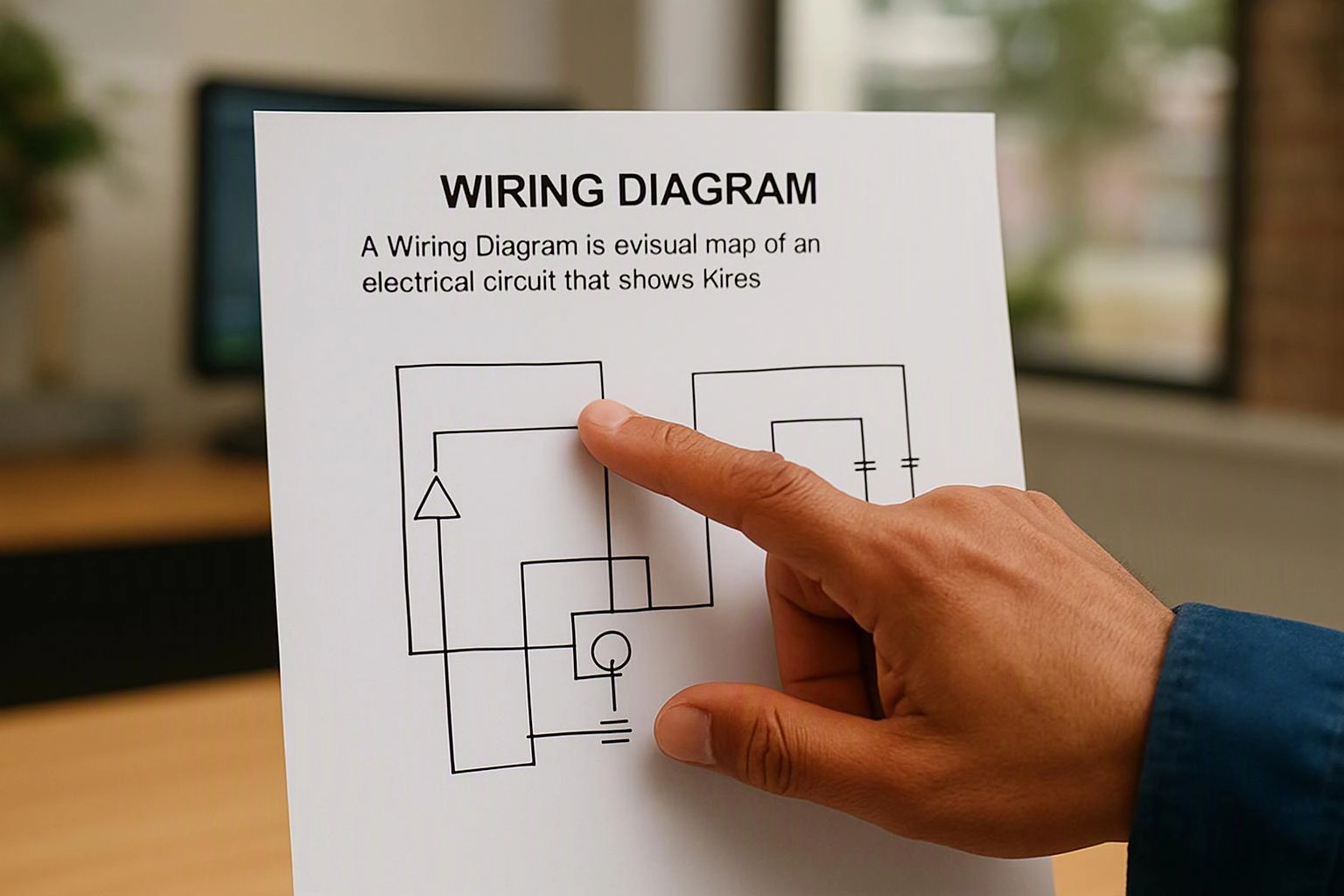
A Wiring Diagram is a visual map of an electrical circuit that shows wires, devices, connections, and power flow. Symbols identify components, while lines show how those components connect. Electricians use the diagram to trace circuits, understand control paths, verify connections, and locate possible causes during electrical troubleshooting.
Quick Facts About Wiring Diagram
Category
Electrical documentation
Used for
Tracing circuit connections
Common confusion
Confused with a floor plan
Also called
Electrical Wiring Diagram, Circuit wiring diagram
Often discussed with
Electrical Troubleshooting
Key Takeaways About Wiring Diagram
- Symbols represent devices, terminals, switches, and circuit paths.
- The diagram helps trace power and control connections.
- A wiring diagram is not the same as a floor plan.
How Wiring Diagram Works
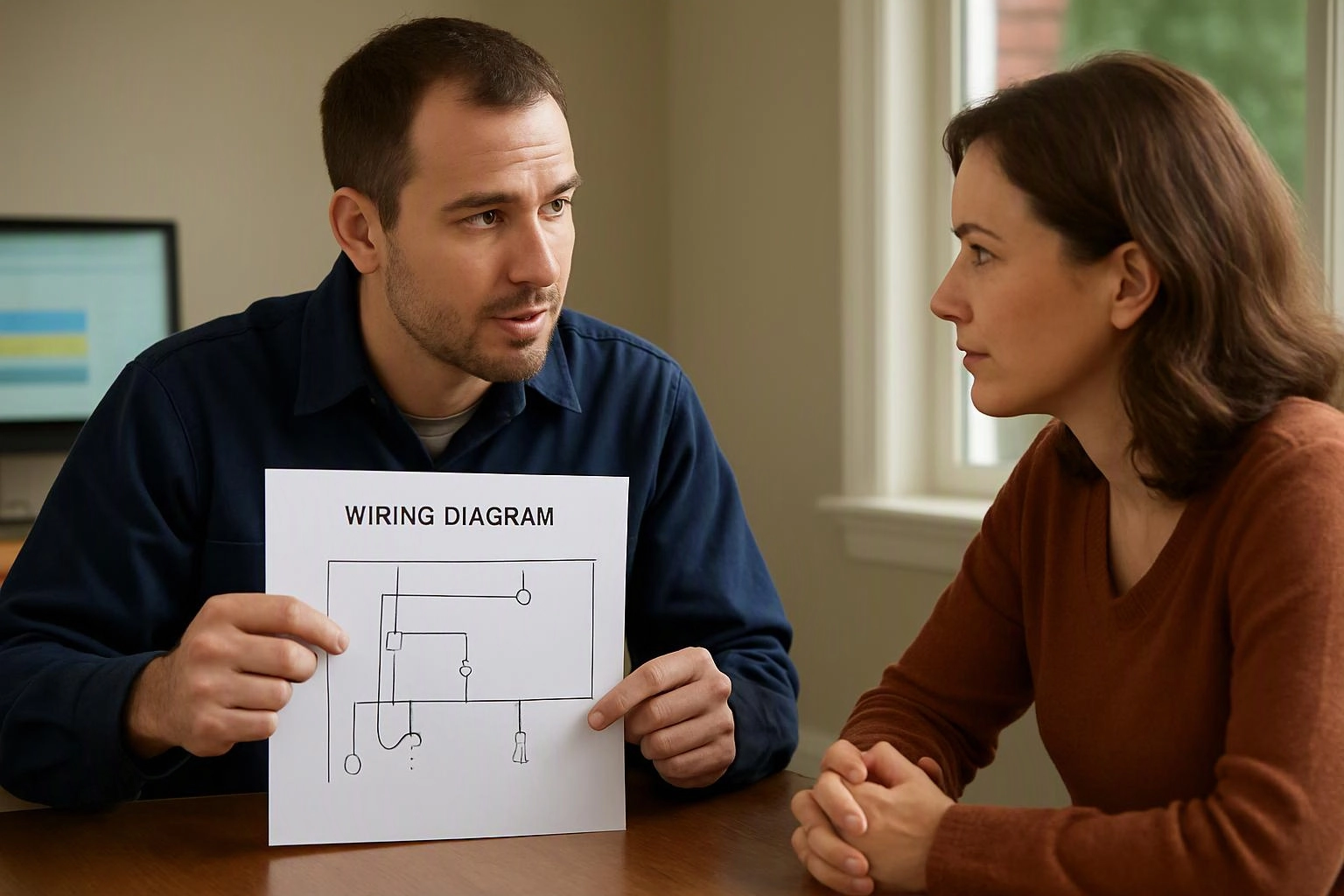
A Wiring Diagram uses standard symbols and labeled lines to show how electrical parts connect within a circuit. The diagram may show a power source, overcurrent protection, switches, loads, and return paths. Labels help match each connection to a terminal or conductor during testing.
Related glossary terms: Branch Circuit, Junction Box, Neutral Wire.
Electricians follow the circuit path from the source toward the load and then through the return path. A Branch Circuit diagram can reveal where a switch controls a light or where a loose connection interrupts power. A Junction Box may also appear when conductors join at an accessible point. The drawing shows circuit relationships, while the installed wiring remains in the building.
From the GMB Electric team
When we troubleshoot, we compare the wiring diagram with the equipment and the installed conductors. We trace power, neutral, grounding, and control paths, then check whether each connection matches the diagram. If field wiring differs, we document the difference before testing the circuit further.
Wiring Diagram in Practice: A Real-World Example
A homeowner reports that a basement light works from one switch but not another. During electrical troubleshooting, a wiring diagram helps identify the traveler wires, common terminals, and light connection so the circuit path can be checked in order.
Related Services
Related Terms
Branch Circuit
A branch circuit is the portion of an electrical system that carries power from a panelboard…
Junction Box
A Junction Box is an enclosed electrical box that protects and contains wire splices, connections, and…
Neutral Wire
Neutral wire is a current-carrying conductor that completes the electrical path from a load back to…
Polarity
Polarity is the arrangement of electrical connections that identifies the intended direction of current or the…
GMB Electric
Have Questions About Wiring Diagram?
Contact GMB Electric for practical guidance on Wiring Diagram and related 24 hour electrician work in Indianapolis.